Ingersoll Rand — Jan to May 2026
Impact Wrench
A half-inch pneumatic impact wrench, rebuilt from the internals outward.
- Role
- Industrial design, ergonomics, rendering
- Timeline
- Jan – May 2026
- Tools
- SolidWorks, KeyShot, foam modelling
- Scope
- Full exterior: housing, grip, trigger, regulator, nose
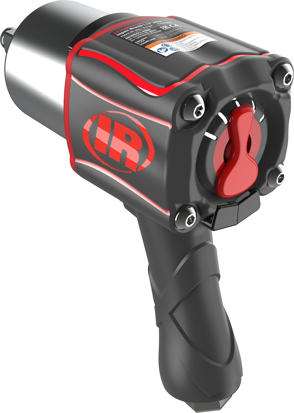
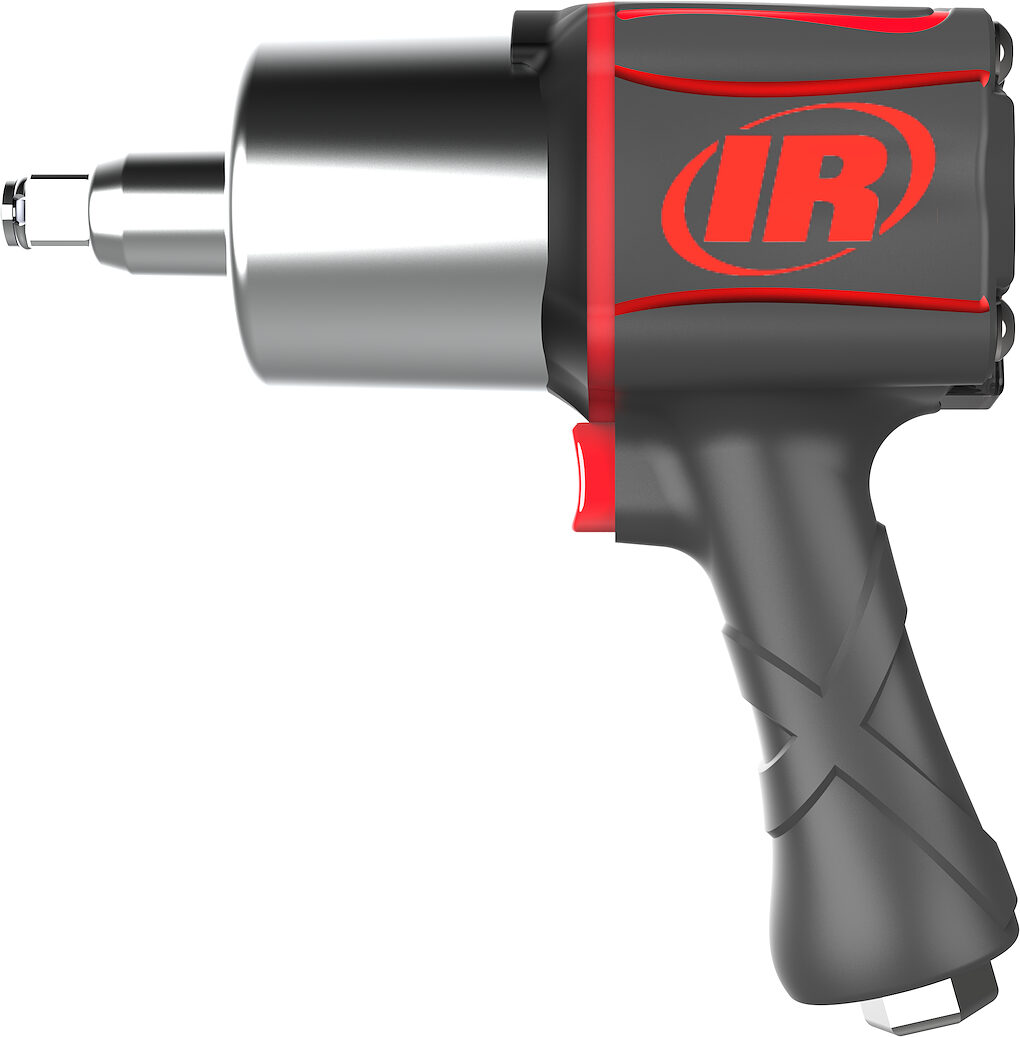
The Brief
Tough and purposeful in the hand, without going front-heavy.
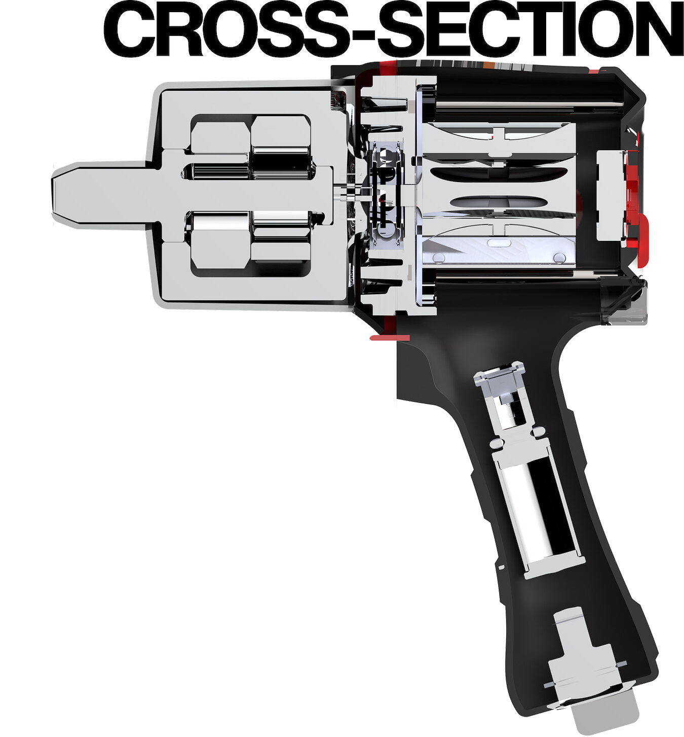
Time in a working shop set the priorities: high torque on stubborn bolts, a compact head for tight spaces, low weight and vibration for long sessions, and a work light that actually reaches the fastener. Every exterior surface was designed around off-the-shelf internal components.
Platform
- Drive
- 1/2 inch
- Max pressure
- 90 psig / 6.2 bar
- Free speed
- 8,500 rpm
Research & Ideation
Shop floor first, foam second, CAD last.
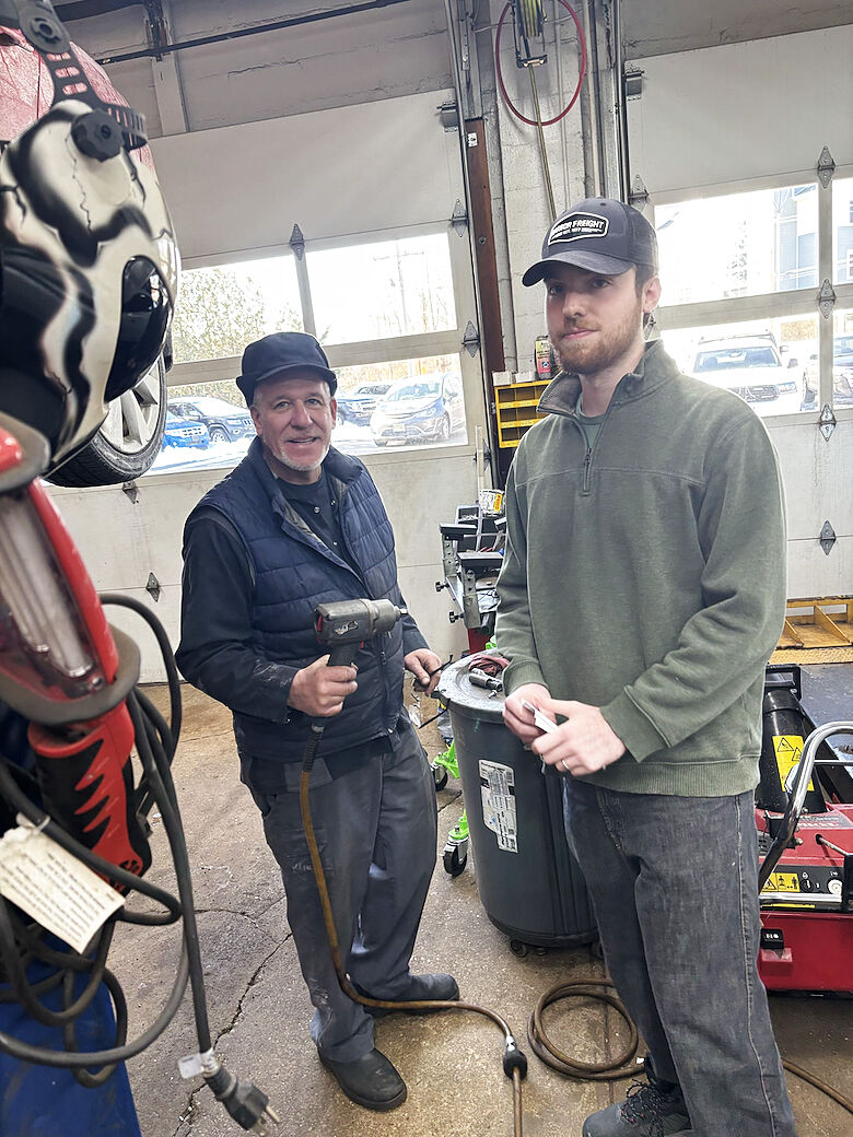
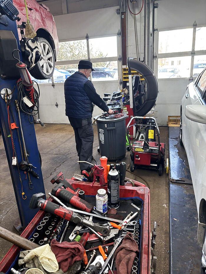
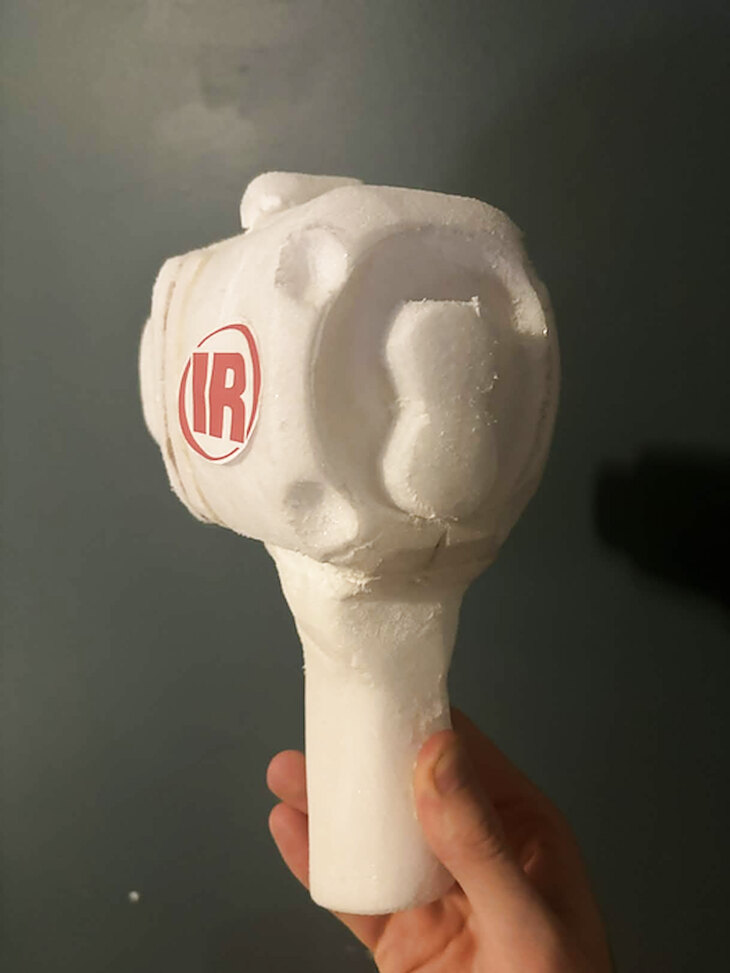
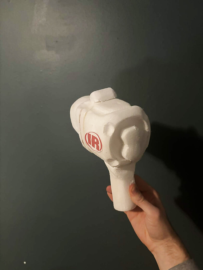
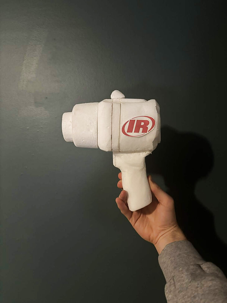
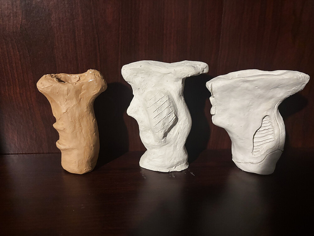
The project started at a working shop, talking to technicians about which tools they reach for and what frustrates them. Shaping the grip in foam was the fastest way to judge volume and balance in the hand — the part hardest to evaluate on screen.
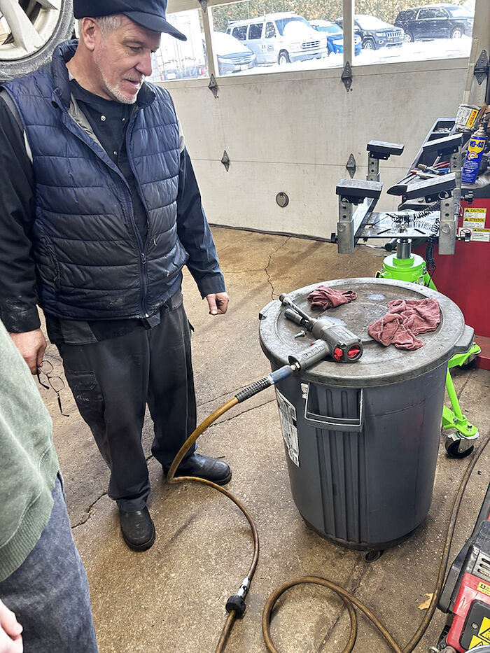
What technicians asked for
- High torque for stubborn bolts
- Compact head for tight spaces
- Lightweight, to cut fatigue
- Durable enough for shop conditions
- Comfortable grip, low vibration
- Balanced, not front-heavy
- Built-in light for visibility
- Easy forward / reverse switch
- Quick socket change
- Air-efficient, less compressor draw
CAD Development
First housing passes, stripped of colour.
Straight out of the foam models the housing went into SolidWorks and stayed in a plain white finish. With the colour gone, the split line, grip section and trigger relief had to hold up on form alone. Red went on nothing but the parts a user actually touches.
Detail
Four decisions that carried the design.
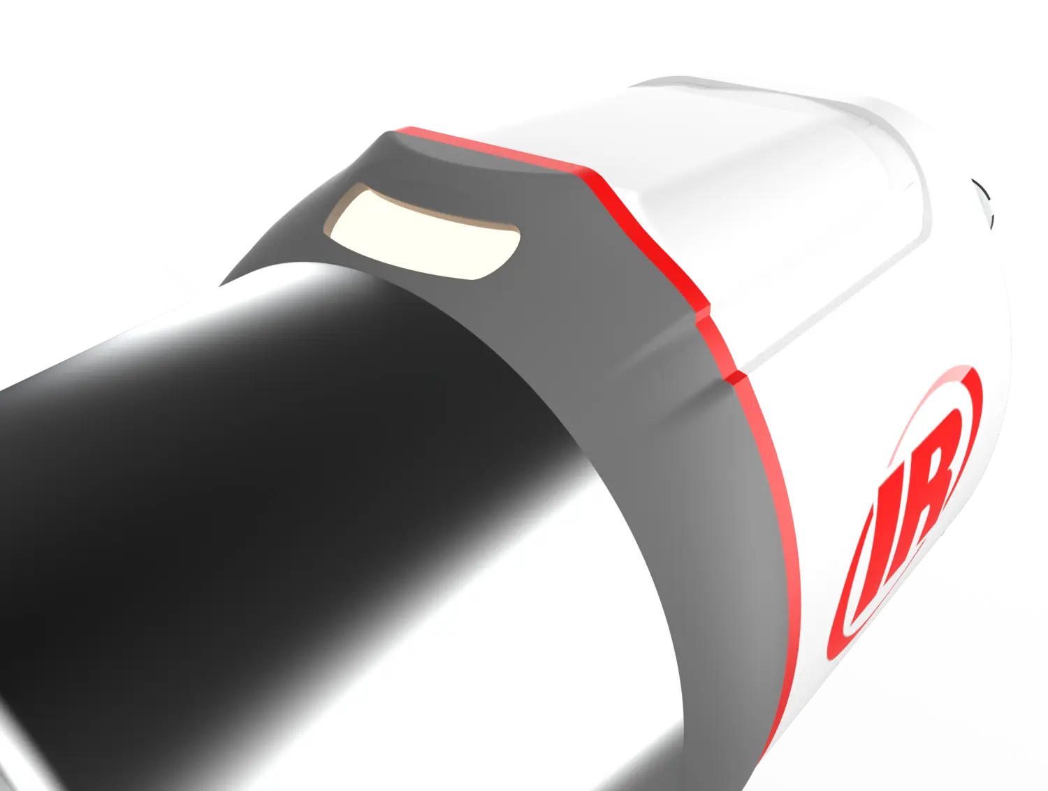
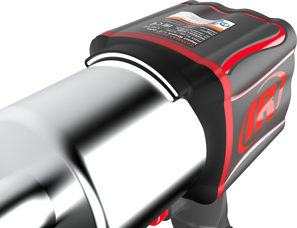
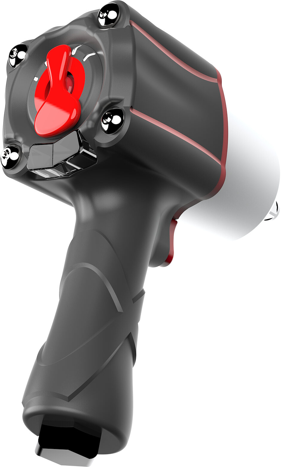
Forward-set work light
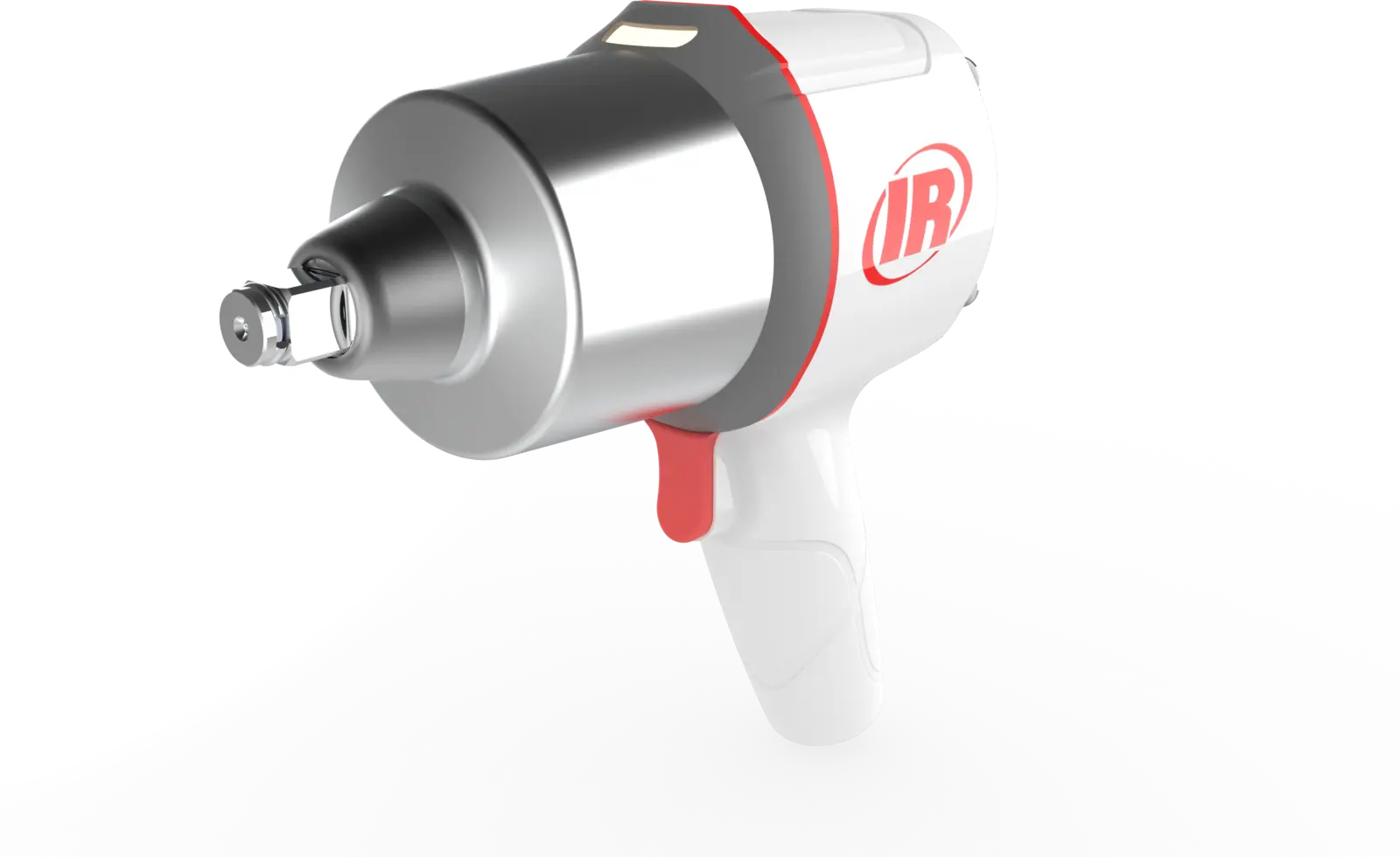
The light moved forward and extrudes outward so the beam clears the socket and tool head instead of being blocked by it. A curved slot spreads it more evenly, cutting the shadow directly in front of the tool.
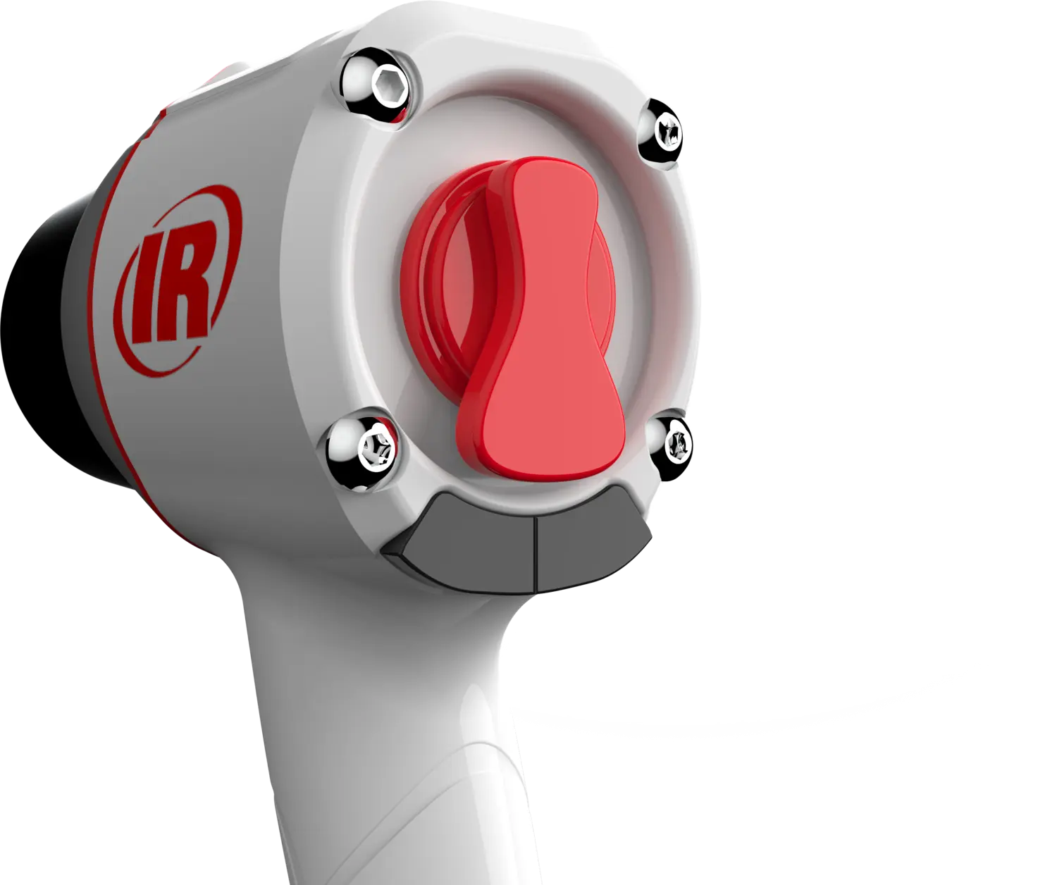
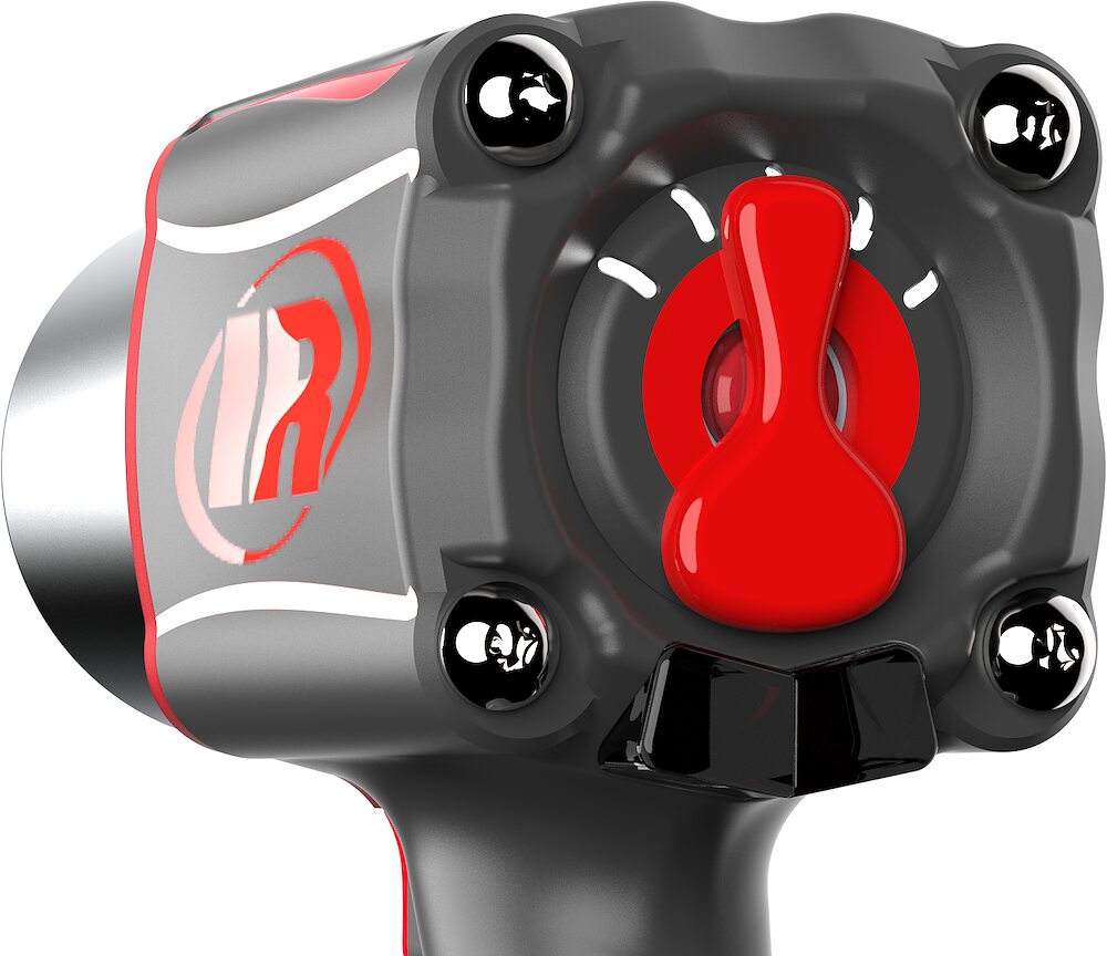
Hourglass power regulator
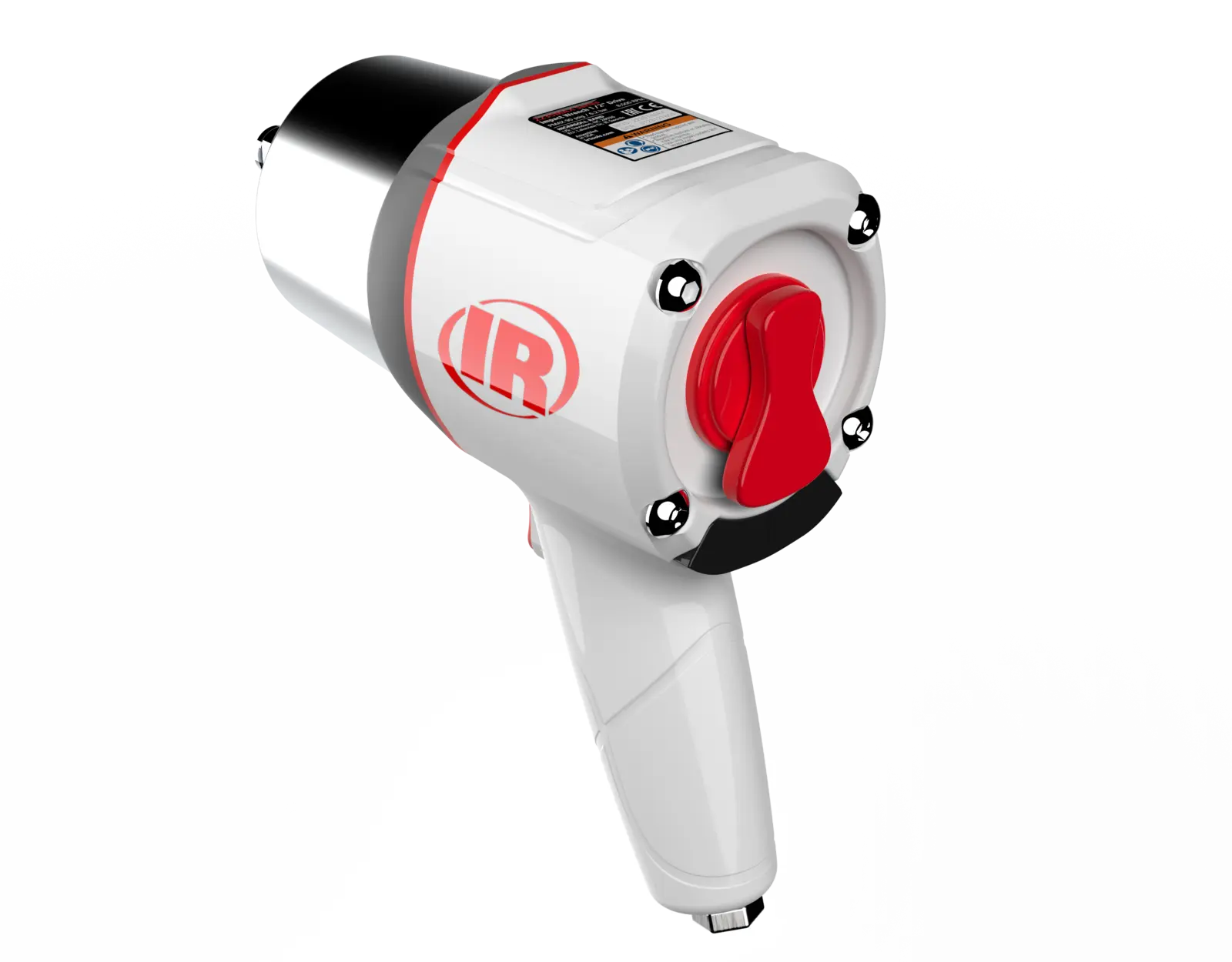
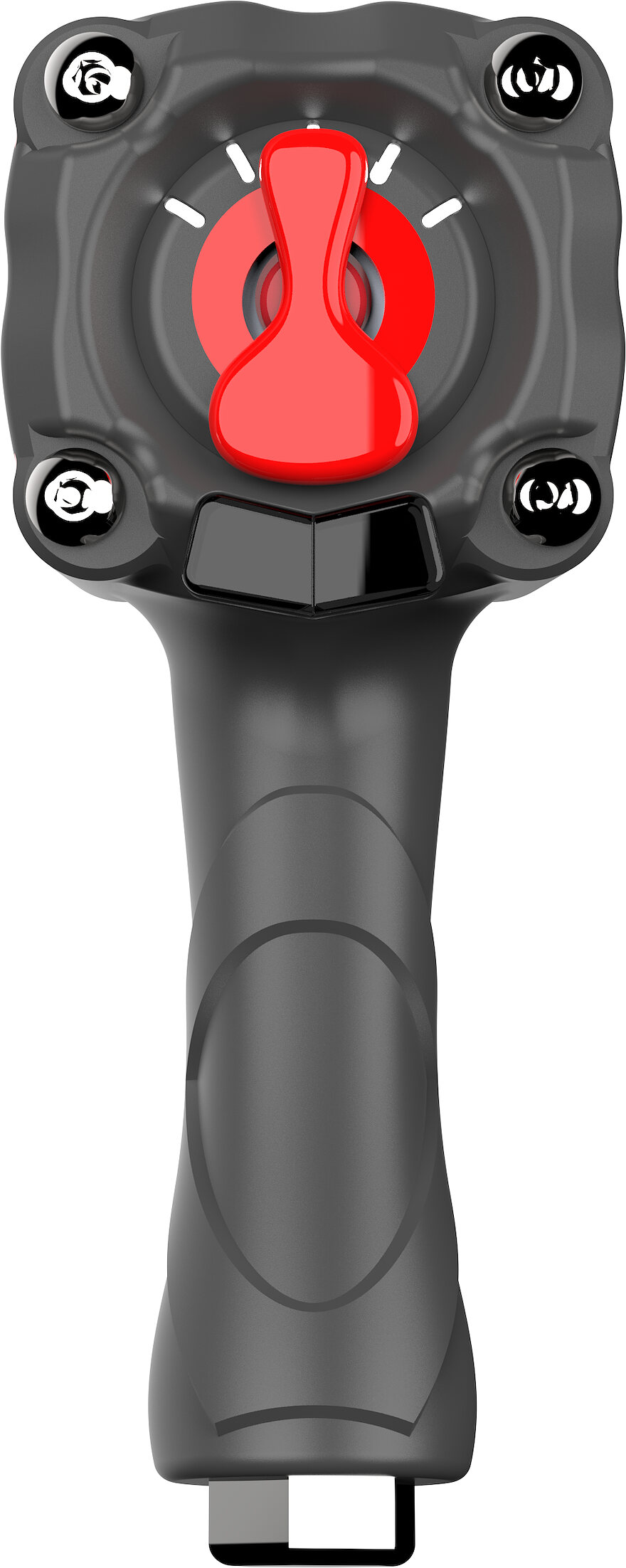
The narrow centre fits a natural thumb grip and makes small power adjustments more precise, while the wider ends are easy to find without looking. LED indicators show the setting at a glance.
Chamfered wrap texture
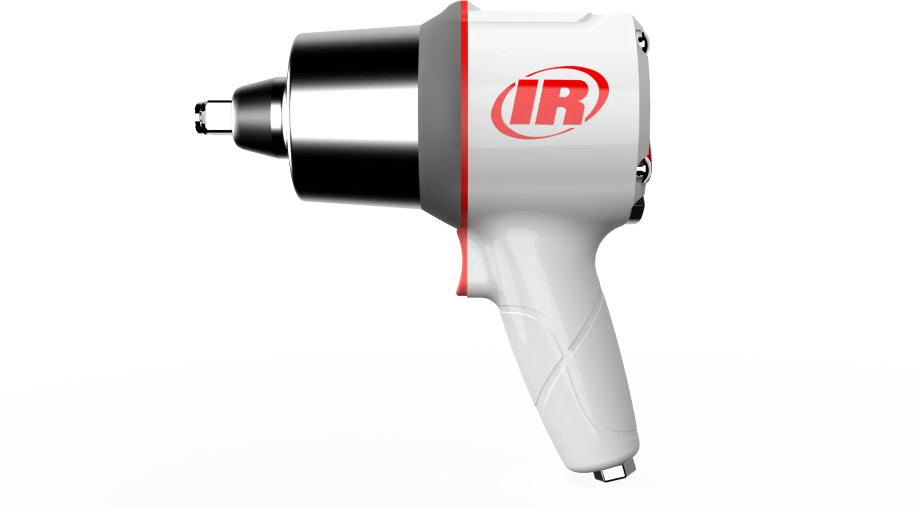
The texture wraps continuously around the handle so grip stays consistent in any hand position and holds traction with oily hands. It doubles as a visual line carrying the form through the body.
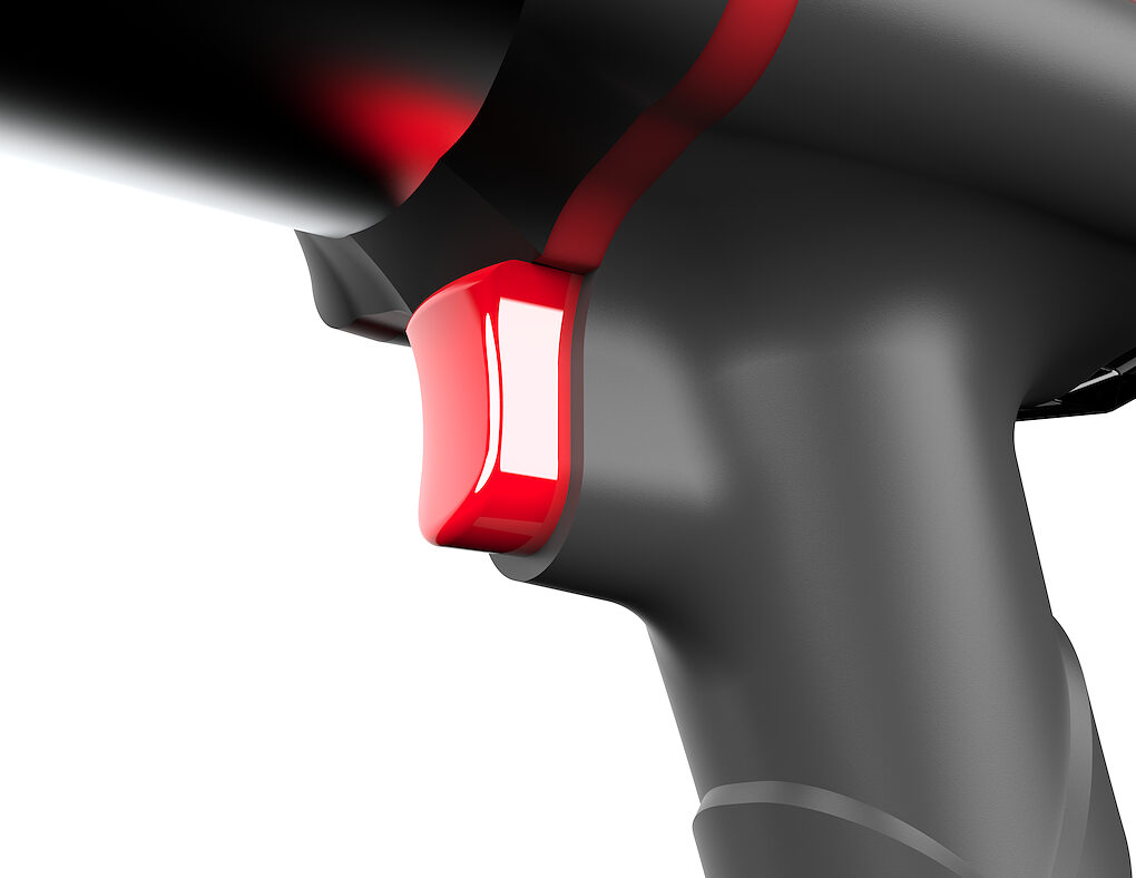
Compound-curve trigger
Curved across multiple planes to match a finger, spreading pressure more evenly than a flat trigger and reducing fatigue over a long job, with finer control through the variable-speed range.
Accessory Concept
Getting the hose off the floor.
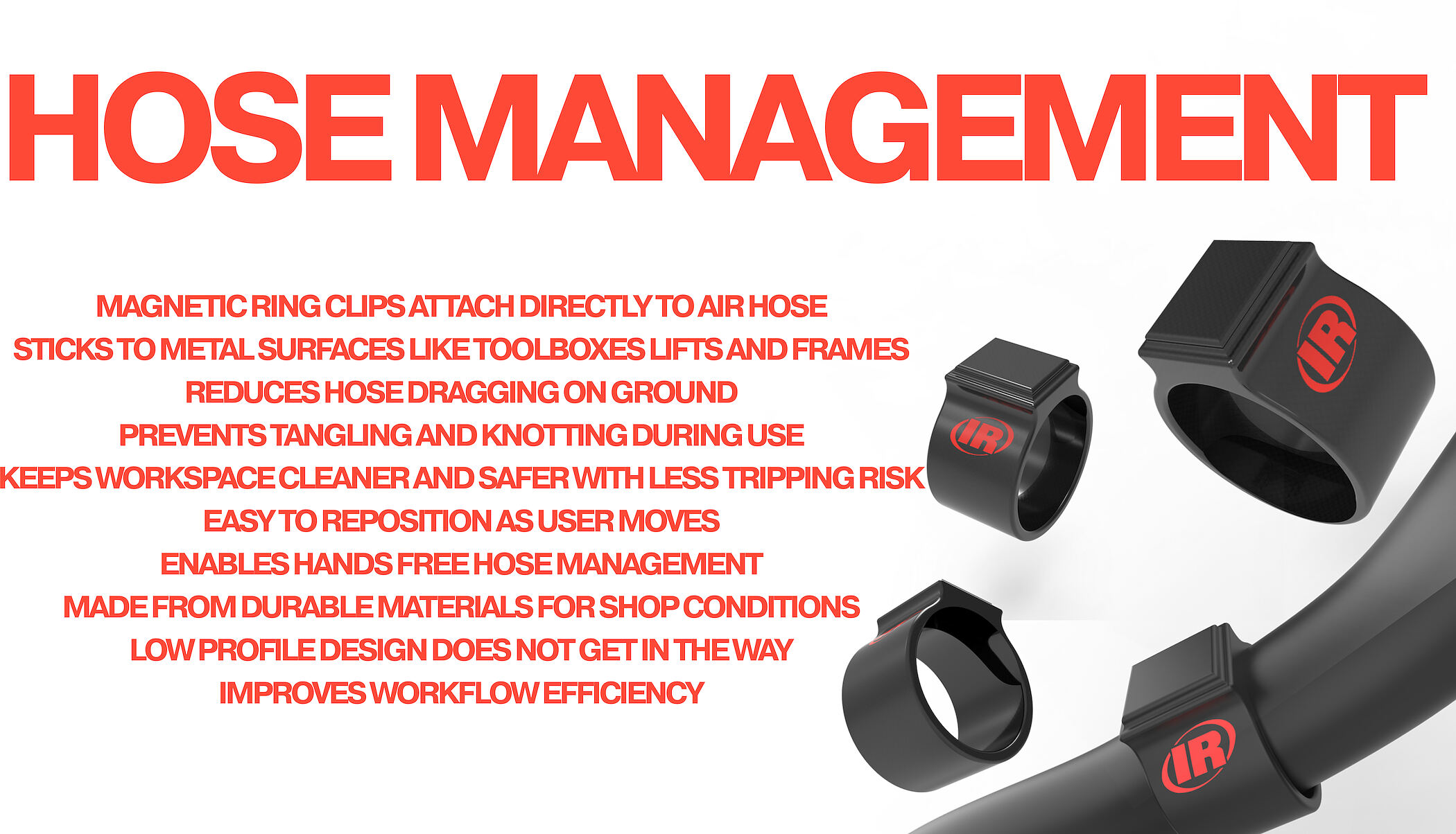
An air hose dragging across a shop floor is a trip hazard and a snag risk. Magnetic ring clips snap onto the hose and stick to toolboxes, lifts and frames, letting the user reposition it hands-free.
Final Design
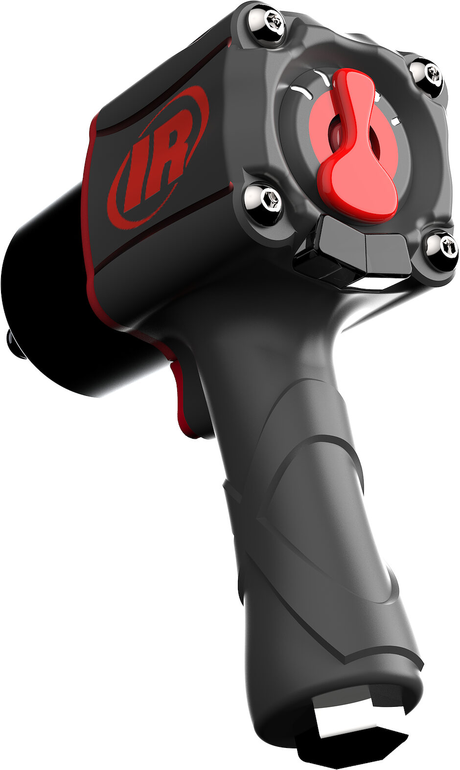
The tool.
Process